Scheme:
The first letter of the ID describes the genera type of the name:
- S stands for signal
- A stands for actuator
- C stands for component
For more information about the naming concept of the ID, the this wiki page: Naming Concept
| Nr. | ID | Name | Signals | Comment |
|---|---|---|---|---|
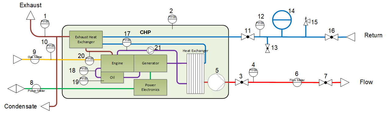
| 1 | S_TM-EG | Temperature Exhaust Gas | PT100 | internal measurement |
| 2 | S_TM-CP | Temperature CHP | PT100 | internal measurement |
| 3 | C_BV-HC_VL_1 | Ball Valve Heating Circuit | ||
| 4 | S_TM-HC_VL | Temperature Heating Circuit | ||
| 5 | A_PU-HC_set | Pump Heating Circuit - setpoint | Controlled by CHP - internal measurement | |
| 6 | S_FW-HC | Flow Water Heating Circuit | 4-20mA & Counter | NeoTower 2.0: 20 mA = 5 l/min |
| 7 | C_BV-HC_VL_2 | Ball Valve Heating Circuit | ||
| 7a | C_BV-HC_contr | Controlable Ball Valve Heating Circuit | DO | Controllable ball valve, can be switched off, when CHP is off in order to prevent unplanned flow through CHP (e.g. from heating circuit) |
| 8 | S_EP | El Active Power | Meassured within the electric system | |
| 9 | S_FG | Flow Gas | Counter | |
| 10 | S_TM-FG | Temperature Fuel Gas | PT100 | |
| 11 | C_BV-HC_RL_1 | Ball Valve Heating Circuit | ||
| 12 | S_TM-HC_RL | Temperature Heating Circuit | PT100 | |
| 13 | C_BV-FD | Ball Valve Fill / Draining | ||
| 14 | C_EV-HC | Expansion Vessel Heating Circuit | NeoTower 2.0: integrated within the CHP | |
| 15 | C_PR-HC | Presser Release Valve Heating Circuit | ||
| 16 | C_BV-HC_RL_2 | Ball Valve Heating Circuit | ||
| 17 | S_TM-ENG_OUT | Temperature Engine Outlet | internal measurement | |
| 18 | S_TM-ENG_IN | Temperature Engine Inlet | internal measurement | |
| 19 | S_TM-OIL | Temerature Oil | internal measurement | |
| 20 | S_TM-EG_bHEX | Temperature Exhaust Gas before Heat Exchanger | internal measurement | |
| 21 | A_PU-ENG_set | Internal Pump - setpoint | internal measurement | |
| CHP-A_CHP | Control Signal CHP | S0 | NeoTower 2.0: | |
| 0-10V | NeoTower 5.0: |
Remarks:
- "Wasserdruck Motorkreis" means pressure of coolant in engine circuit
- max. pressure of coolant in engine circuit: 2.7 bar
- for the CHP to run and to modulate: active "Strom Automatik" and make sure there is a "Zeitprogramm" set that allows modulation

Data Sheets:
NeoTower 2.0 (SF1):
Remeha (Stirling, SF4):
NeoTower 5.0 (MF5):
Wolf GTK 18E-03 (MF5):
Minimum Gas flow rate:
Necessary to define the cero flow condition and the TimeMeanValue for calculating the flowrate
| \dot V_{Gas}=\frac{T\cdot p_n}{H_i \cdot T_n \cdot p}\cdot\frac{(P_{el}+P_{heat})}{\eta}= 1.494 \cdot \frac{(P_{el}+P_{heat})}{\eta} [\frac{l}{kW \cdot min}] |
\dot V_{min} \: [l/min] | max time per count [s] | \dot V_{max} \: [l/min] | min time per count [s] | cero flow condition [s] | TimeMeanValue [s] | |
|---|---|---|---|---|---|---|
| NeoTower 2.0 | 7.3 | 82 | 10.8 | 56 | 90 | 84 |
| NeoTower 5.0 | 16.8 | 36 | 25.2 | 24 | 40 | 36 |
| Remeha | ~10.5 | ~57 | ~39 | ~15 | 60 | 23 |
| Wolf GTK 18 | 50.8 | 11.8 | 83.7 | 7.2 | 15 | 11 |