This control VI does not contain any logic that provides operation set points for the booster heat pump. Instead it is more comparable to a hardware abstraction layer.
The tasks of this control vi is to convert intput signals from the control strategy / management implementation to the BHP's actuators (including its thermal storage and the grid side pump).
Additionally this VI implements hardware requirements as the minimum runtime of the BHP and flushing the evaporator after turning off the heat pump.
The control VI can be run in automatic or in manual/direct control mode.
A pictured description on the navigation in the BHPs touchdisplay and how to monitor and change settings there is attached further down this page.
Automatic control
Inputs:
0 - Off |
|
0 - Direct_Heat_Exchanger | |
|
|
| |
| |
| only in heating mode; activates the el. heater and sets its el. power |
| a value >0 activates the PI controller for the return temperature. Warm water from the BHP flow is mixed to the return pipe to reach the set temperature |
| depending on parameter GridPumpControlMode a flow rate or temperature difference can be set by controlling the grid pump rpm |
Outputs:
- Heating power [kW]
- Cooling power [kW]
- Electric power [kW]
- COP [−]
- EER [−]
- Heating / Cooling or Domestic Hot Water [bool]
- Temperatures, flow rates and humidity. - for the positions of the sensors BHP - Hardware
Parameters (default values marked orange):
0 - direct | sets the valves connecting to storage and heat sink storage is bypassed and only used to balance the flow rates of production and consumption |
0 - VL-RL | sets the valves connecting to the grid supply-to-return |
0 - Set_T_VL | determines to which unit the heat pump is controlled to set a flow temperature, the corresponding operation mode has to be set on the display of the BHP. |
| Usage of integrated heating rod as a cold sink |
| Set Return Temperature for integrated heating rod when used as a cold sink |
| Temperature set value for DHW heat exchanger on consumer side |
0 - Off | Grid Pump is off |
| minimum runtime of the BHP's compressor in seconds; changes between heating and cooling mode or turning the BHP off take only effect after this time has elapsed |
| minimum downtime between startups of the BHP in seconds |
Manual/direct control
When the boolean input "ManualControl" to the model is set to true, all actors can be controlled via 0-10V or DO signals.
Touchdisplay and menu of the BHP
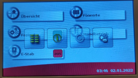
This is the start window. |
By clicking on “Übersicht” on the start window, the hydraulic schematic with some relevant sensor and actor values of the BHP unit appears. |
When going to the “Fixwerte” menu from the starting window, the user can check and change some general settings of the BHP. Whenever asked for a password, use the default one “64”. |
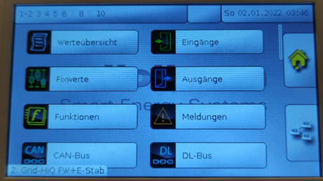
Touch and hold (~5sec.) somewhere on the start window until the menu of the next figure appears. |
To access the different controllers of the BHP, tip on the network icon on the bottom right. |
In this submenu you can choose which controller to access. They are distinguished by their “Knotennummer”. |
By using the buttons on this menu, the inputs, outputs and other signals of the currently selected controller are accessible. |
To check for the cooling activation signal, select controller “Knoten 2”, then click on DL-Bus and then “Eingänge”. The relevant signal is “Anforderung Kühlung”. Here a value of -9999°C means cooling is requested and positive value of 9999°C means no cooling is requested. The pin alignment deviates from the manual due to an error fix. |
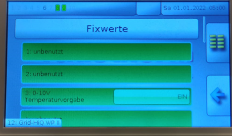
The standard factory settings did not provide the option to set the compressor rpm externally. To enable this an additional boolean variable was included. To to monitor its value and change between temperature and rpm control, select “Knoten 12”, then click on “Fixwerte”. Here, the signal value “EIN” indicates temperature control and “AUS” rpm control respectively. Click on the light green button to change the value. |