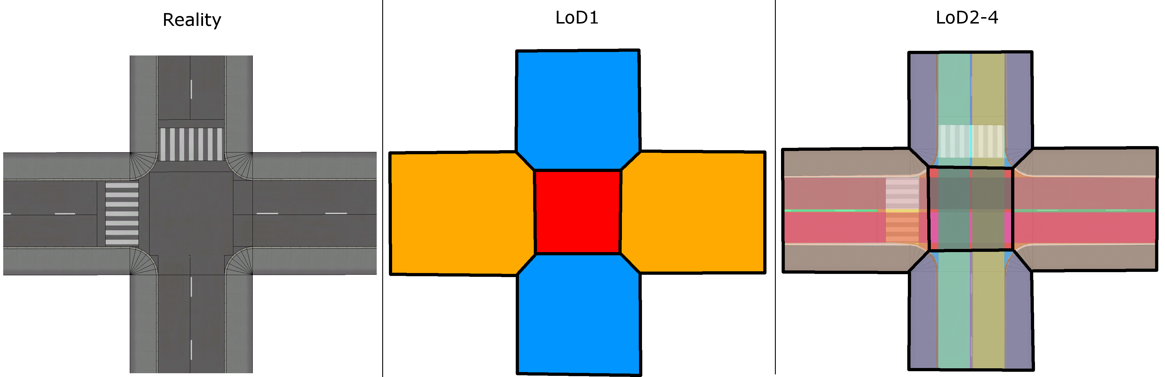
This section describes a conceptual model for representing street space in different levels of detail within digital city models. First, deficits of the current Transportation Model of the CityGML2.0 standard are identified. Then, based on these deficits, a proposal for a revised Transportation Model is presented. In the last parts of this section, real world scenarios and their possible representation according to the current CityGML2.0 standard are presented.
The ‘Transportation Model’ in CityGML2.0 is mainly designed to define a basic framework for a uniform modelling concept of street space objects and is intended to complement and not to replace existing standards such as GDF. Nevertheless, some deficits of the current ‘Transportation Model’ can be identified.
Insufficient specifications
- It is unclear which axis should be used to represent streets in LoD0 (roadway- or lane-axis).
- The possibility to represent intersections as nodes in LoD0 is implied by the defined geometry class GeometricComplex but not specified otherwise.
- Roads modelled in LoD1 are to be represented by MultiSurface geometries. It is not clear which objects of street space should be included in this representation.
- The segmentation of a TransportationComplex into multiple Road, Track, Square, or Railway objects is possible but not specified any further. Until now it is possible to represent the entire street space of a city by just one Road object.
- Intersections and roundabouts are not represented explicitly.
Missing stationing / linear referencing concept
Attributes like speed limits can change in the course of a road. In order to represent these changes the corresponding object would have to be split in smaller parts with individual attributes. This is inconvenient and impractical. Sometimes attributes like speed limits may vary time dependent or may depend on symbols shown on sign gantries. This problem could be solved by introducing a stationing or linear referencing system. Attributes could then be specified for certain sections of a transportation object without having to split its geometry.
Other points of criticism
- An additional class RoadSection could define a clear segmentation concept for road network objects.
- It is not clear if TrafficAreas representing parking lots should be part of the subclass Road or Square.
- The graphic used in the CityGML2.0 standard to illustrate Squares can be misinterpreted. The displayed intersection should be part of the subclass Road and not Square. Squares should be defined as plazas mainly used by pedestrians or large areas with sealed surfaces like parking lots.
Intersections belong to multiple streets. It is not clear how to model this circumstance while avoiding a redundant representation.
The main difference between LoD3 and LoD4 models is the possibility to represent interior structures of buildings such as individual rooms. For many other thematic models, including the ‘Transportation Model’, this can lead to absurd results.
Subsurface structures such as material layers are not considered yet.
Clearance spaces could be represented by extruding road- or pathway footprints. This is not specified yet.
Geometric and semantic subtleties such as manholes, drains or roadway damages are not defined.
These points of criticism as well as potential user requirements serve as inspiration for a proposal of a revised ‘Transportation Model’.
Data Model
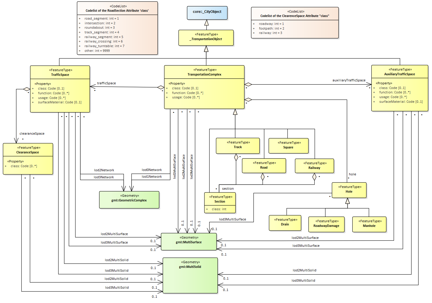
First an advanced data model of the CityGML ‘Transportation Model’ is presented. The basic structure of this model with TransportationComplex as main class divided into 4 subclasses Road, Square, Track, and Railway remains in place. From LoD2 newly labelled TrafficSpaces and AuxiliaryTrafficSpaces can be spatially modelled by MultiSurface as well as MultiSolid geometries. Furthermore, linear representations of street space should not be limited to LoD0. By specifying which axis of a street should be used, linear representation with different levels of complexity become possible. Squares are defined as large sealed surfaces such as plazas or parking lots. By introducing a new class called Section a segmentation of Road, Track, and Railway objects is possible and further specified using a class attribute with corresponding code list values. Moreover, representations of subtle objects such as manholes or roadway damages can be allowed as a LoD3 representation. Clearance space models in the form of solid geometries representing free space above traffic surfaces are proposed together with a corresponding code list defining possible class attribute values. The usage of XLinks avoids the redundant representation of street sections that are part of multiple streets in CityGML instance documents. This data model with newly introduced classes, attributes, geometries as well as a revised LoD concept is shown as UML diagram in figure 2 and explained in detail in the following subsections.
UML Diagramm of a revised CityGML Transportation Model
Four Levels of Detail instead of Five
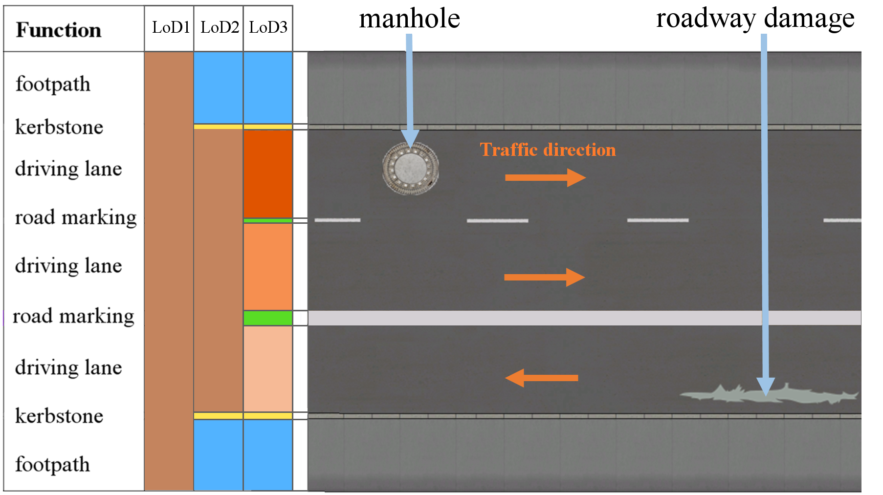
Löwner et al. (2016) propose a new LoD concept representing all city features in just four levels of detail. Following this idea, it is proposed to model street space objects of the ‘Transportation Model’ in LoD0-LoD3. The following image shows a ‘real world’ street segment with multiple thematic parts. It is indicated that an areal LoD1 representation should contain the entire width of the street, including sidewalks, kerbstones or barriers. A more detailed segmentation into TrafficSpaces and AuxiliaryTrafficSpaces should be realised starting from LoD2 while LoD3 additionally allows the representation of subtle structures such as manholes or roadway damages. This is very similar to the way how building models are represented thematically more detailed in CityGML with increasing LoD.
In addition to areal models, the following image further specifies which street axis should be used for linear representations in each LoD and also gives an example for the representation of roadway damages in LoD3. These holes in a street surface can extend over more than one road section and therefore should be modelled as a separate class (and not as a part of a Section) and spatially represented by MultiSurface geometries.
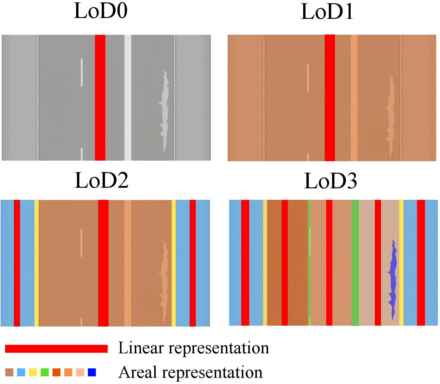
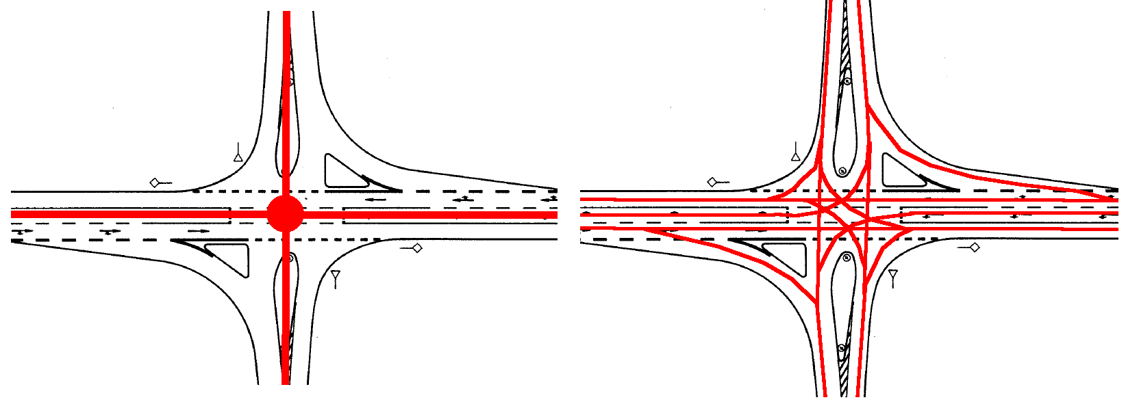
As long as roadways are not topologically separated, streets are represented by a single centreline per driveway in LoD0 and LoD1. Starting from LoD1, street space can be modelled by linear and/or areal objects respectively. In addition to the driveway centreline, linear representations for footpaths and bikeways become possible in LoD2, thus enabling a more detailed thematic decomposition of street space. While driveways are still represented by a single TrafficSpace object in LoD2, LoD3 representations finally contain one TrafficSpace object for each individual driving lane. The following image shows a direct comparison of linear network representations in LoD0 and LoD3. While lod0Netwoks are modelled with one axis per driveway and section (defined in the following paragraph) connected with nodes representing intersections, lod3Networks contain separate lines for each individual driving lane, following every possible way a car could take. This automatically implies a predecessor/ successor concept useful for some applications.
Introducing sections
A proposed concept to divide street networks into several sections is illustrated in the following image.
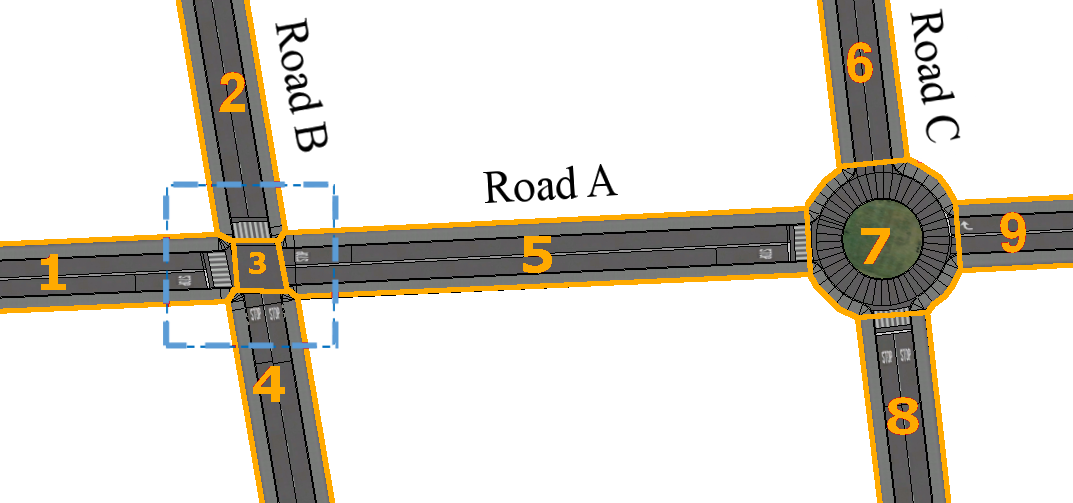
Road objects representing an entire street could be split into 3 different types of sections declared by class attribute values defined in a corresponding code list. These types are ‘road_segments’ (Nr. 1, 2, 4, 5, 6, 8 and 9), ‘intersections’ (Nr. 3) and ‘roundabouts’ (Nr. 7). In the given example Road A consists of Sections Nr. 1, 3, 5, 7 and 9 while Road B is composed of Sections Nr. 2, 4, and also 3. This means Road A and Road B share Section 3. In order to avoid a redundant representation of this shared object, XLinks are used in the CityGML instance document to reference the shared section. This is visualized in the following object diagram.
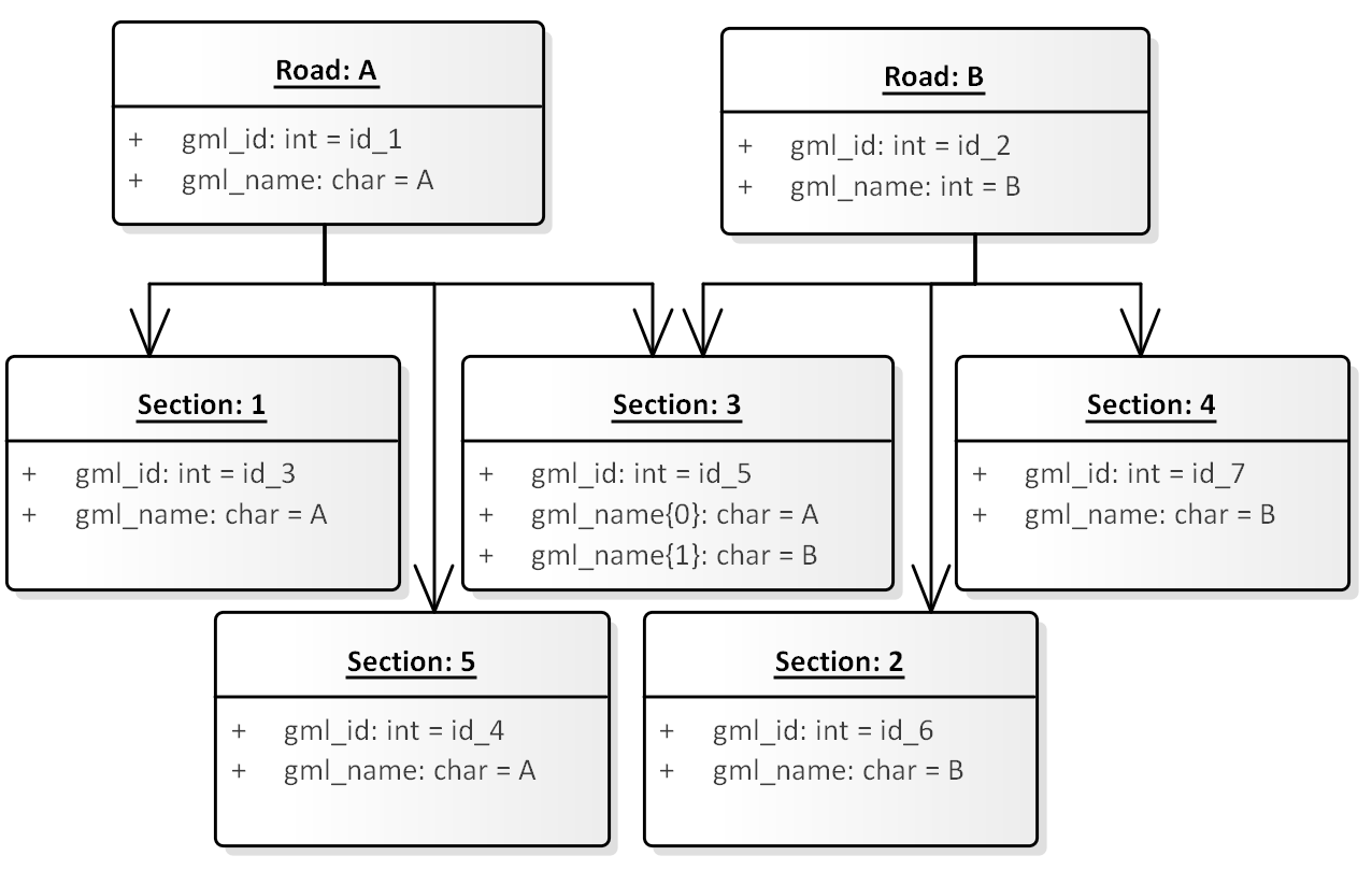
Usage of the XLink concept to avoid redundant representations is explained in more detail in the CityGML specification document (Gröger et al. 2012).
Definition: Intersection Area
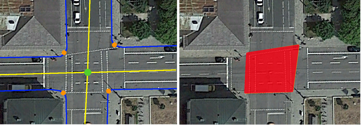
Intersection areas, that are part of multiple streets at the same time, can be defined the following way.
- Street centerlines
- Centerline intersection
- Street surface border
- Points on 'Street surface border' with smallest distance to 'Centerline intersection'
- Intersection area
In this section a number of real world scenarios is examined and possible ways for representations in LoD0 and LoD1 according to the CityGML2.0 Transportation Model are discussed. The given examples focus on street surfaces (used for vehicle movement) only, and don't take into account other street space objects such as sidewalks or plazas. For each scenario a 'real word' example is generated using the Software CityEngine. Each of these objects would be assigned to one specific 'Road' feature.
Most common street scenarios
The most common scenarios are listed below and can be examined by clicking on a specific heading.
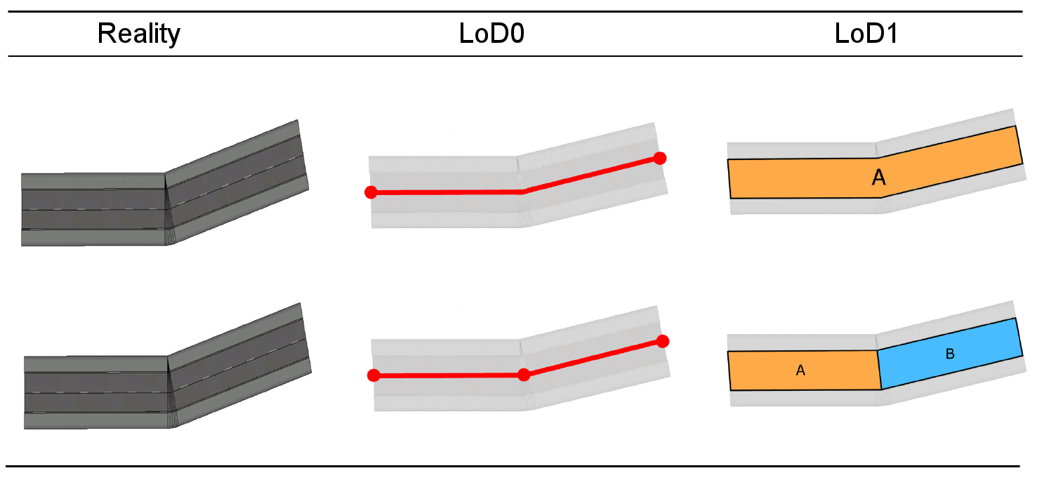
The simplest configuration is a road made of two consecutive street segments. Those segments can be represented as line feature following the path of the road in LoD0 and as areal polygons covering the streets surface in LoD1. Two different scenarios can be distinguished. If both segments belong to the same street (same name and attributes). In this case one line/polygon feature is sufficient. In the case of two different streets (different street name or other separating attribute such as surface material) two indivdual segments should be introduced in both levels of detail. Individual segments should be introduced when a segnificant attribute such as the street name or the surface material changes in the cours of a continuous road.
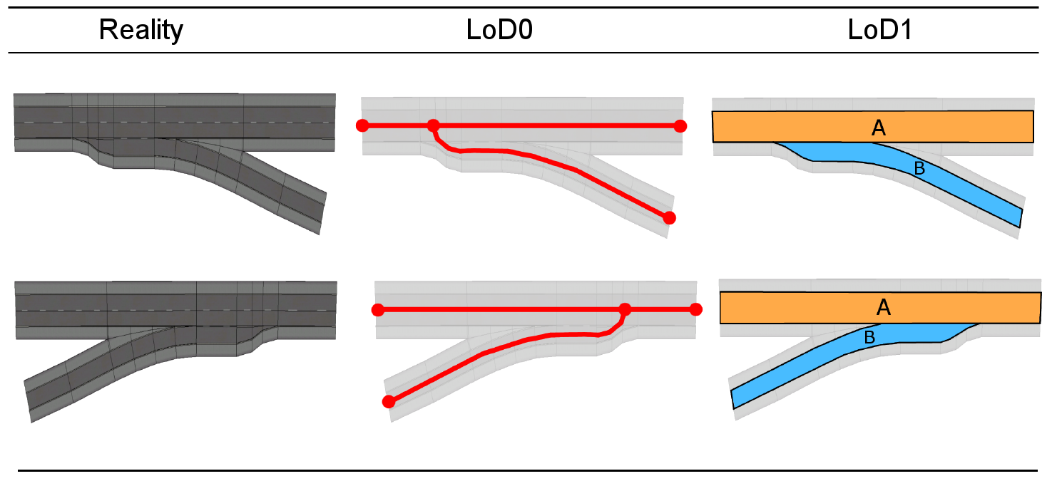
Street exits and driveways should be modelled as shown in the image below. In LoD0 this is represented with a line following the course of the driveway and intersecting with the main road segment. The main road is represend by one continuous segement in LoD1.
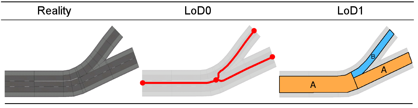
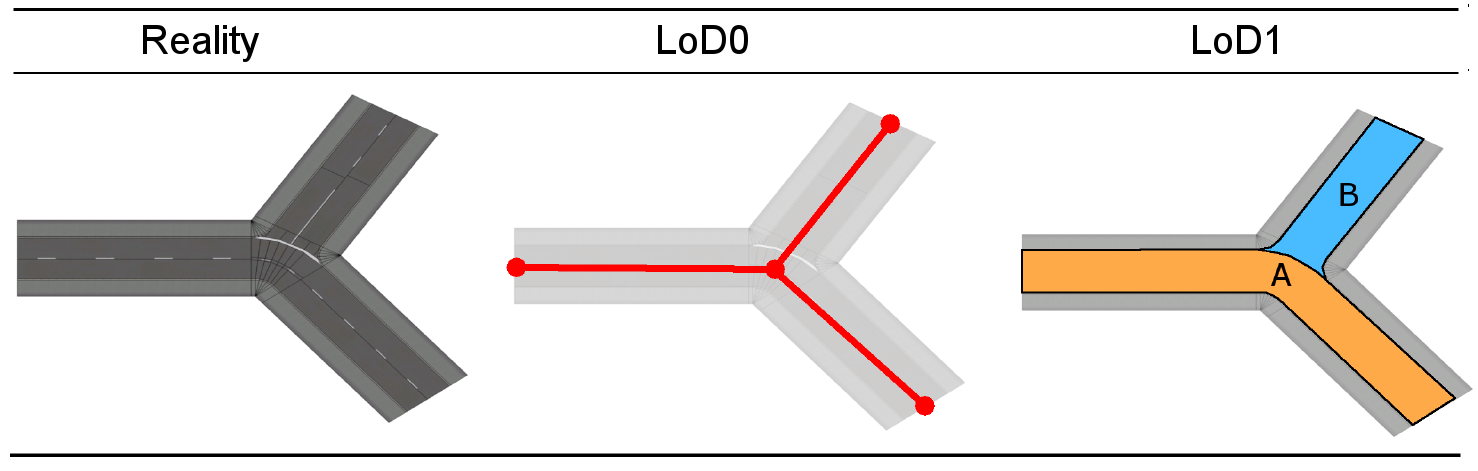
A street splitting into several branches should be considered by an appropriate representation.
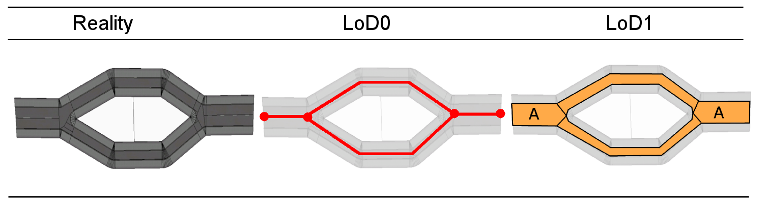
As long as roadways are not topologically separated, streets are represented by a single centreline per driveway in LoD0. However, if two or more lanes of a street are spereated by several meters, individual object for each segment should be introduced in LoD0 as well as in LoD1 representations as shown below.
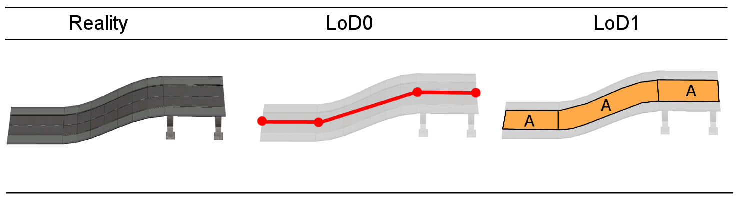
Ramps or other artificial constructions causing a change in a street's elevation should be represented by introducing individual sections.
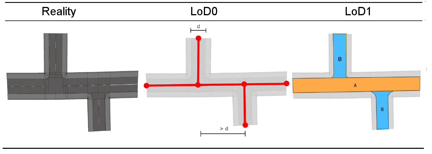
If two intersections are seperated by more than the width of the widest street (d), no intersection area should be introduced. The main road should be represented as one continuous street.
For 3 way intersections there are two basic scenarios. Either two of the intersecting segments belong to the same street or all three segments belong to different streets. In the first case, the two segments belonging to the same street should be represented as one continuous street segment (first example shown below). The second case could be represented in tow different ways. First, by introducing a intersection area belonging to all streets or second, 3 touching segments without an intersection area. For all cases the representation in LoD0 is the same.
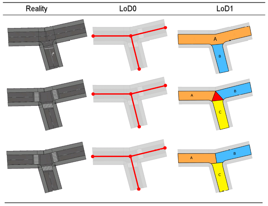
Traffic turning right/left having priority is basicly just a specific case of two segments belonging to the same street.
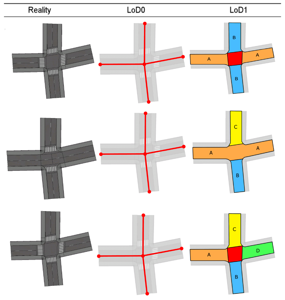
For 4 way intersections there are basically three scenarios. The most common of those is shown in the top row of the following graphic. Here two seperate streets intersect and continue after the intersection. In this case an intersection area, beloning to both streets equally should be defined. The second scenario contains three different intersecting streets. In this case the two street segments beloning to the same street should be represented continuously. The third possible scenarion contains four street segments beloning to four different streets. In this case an intersection area should be used. Note that the LoD0 representation for all three scenarios is the same.
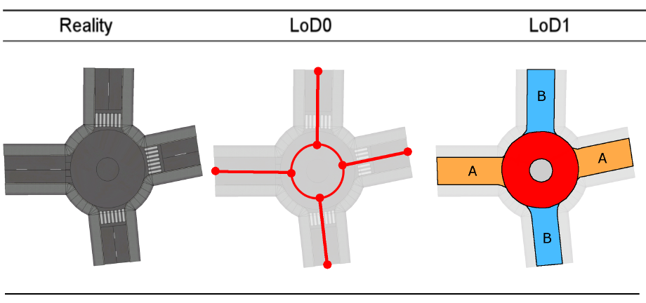
Roundabouts should be represented in LoD0 and LoD1 as shown in the graphic below.
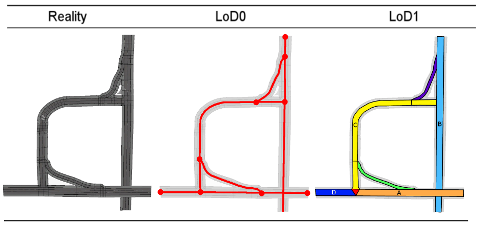
Most more complex scenarios can be represented using combinations of the examples shown above.
Street space can be further decomposed into TrafficAreas and AuxiliaryTrafficAreas. Each of these Sub-Level-Features can be assigned to corresponding Top-Level-Features (Road, Square, Track) via XLinks or matching parent_id attributes.