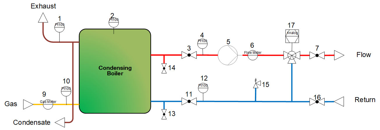
Sheme:
The first letter of the ID describes the genera type of the name:
- S stands for signal
- A stands for actuator
- C stands for component
For more information about the naming concept of the ID, the this wiki page: Naming Concept
| Nr. | ID | Name | Signals | Comment |
|---|---|---|---|---|
| 1 | S_TM-EG | Temperature Exhaust Gas | PT100 | |
| 2 | S_TM-CB | Temperature Condensing Boiler | PT100 | |
| 3 | C_BV-HC_VL_1 | Ball Valve Heating Circuit | ||
| 4 | S_TM-HC_VL | Temperature Heating Circuit | ||
| 5 | A_PU-HC_VL | Pump Heating Circuit | controlled by Boiler | |
| 6 | S_FW-HC_VL | Flow Water Heating Circuit | 4-20mA & Counter | CGB 20: 20 mA = 20 l/min |
| 7 | C_BV-HC_VL_2 | Ball Valve Heating Circuit | ||
| 9 | S_FG | Flow Gas | Counter | |
| 10 | S_TM-FG | Temperature Fuel Gas | PT100 | |
| 11 | C_BV-HC_RL_1 | Ball Valve Heating Circuit | ||
| 12 | S_TM-HC_RL | Temperature Heating Circuit | PT100 | |
| 13 | C_BV-HC_FD_1 | Ball Valve Heating Circuit | ||
| 14 | C_BV-HC_FD_2 | Ball Valve Heating Circuit | ||
| 15 | C_PR-HC | Presser Release Valve Heating Circuit | ||
| 16 | C_BV-HC_RL_2 | Ball Valve Heating Circuit | ||
| 17 | A_MX-HC | Mixing Valve Heating Circuit | 0-10V | SF1: Mixing valve, to control the return temperatuer (student course) and to block flow when CHP is operating |
CB-A_CB | Control Signal Condensing Boiler | 0-10V | 0-2V: Off 2-10V: Modulation regarding Power (config 51), or Temperature (config 52) |
Data Sheets:
CGB 20 (SF1, SF2):
for house 1 CGB-2-14 (14 kW) was delivered and installen
access to "Fachmannebene" via password "1111"
CGB 50 (MF5):
Gas flow rate:
Necessary to define the cero flow condition and the TimeMeanValue for calculating the flowrate
| \dot V_{Gas}=\frac{T\cdot p_n}{H_i \cdot T_n \cdot p}\cdot\frac{(P_{el}+P_{heat})}{\eta}= 1.494 \cdot \frac{(P_{el}+P_{heat})}{\eta} [\frac{l}{kW \cdot min}] |
with
T - measured temperature
p_n - norm pressure
H_i - lower heating value of the heating medium
T_n - norm temperature
p - measured absolute pressure
P_{el}, P_{heat} - electric / heat power
\eta - efficiency
\dot V_{min} \: [l/min] | max time per count [s] | \dot V_{max} \: [l/min] | min time per count [s] | cero flow condition [s] | TimeMeanValue [s] | |
|---|---|---|---|---|---|---|
| CGB 14 | 2.7 | 216 | 21.3 | 28 | 200 | 42 |
| CGB 20 | 5.4 | 111 | 28.1 | 21 | 110 | 32 |
| CGB 50 | 16.2 | 37 | 71.7 | 8.4 | 40 | 13 |
4 Kommentare
Unbekannter Benutzer (ge97bug) sagt:
24. Oktober 2020Maybe start here first with where condensing boiler is place in the lab with a photo of it where we mark or the valves etc that you're referring to here
Unbekannter Benutzer (ge79biy) sagt:
18. September 2022Unbekannter Benutzer (gu62xur) sagt:
19. September 2022Better?
But I don't understand what you mean with the ASHP, it is done the same way, no?
Unbekannter Benutzer (ge79biy) sagt:
19. September 2022My quesstion is if the Datasheets will be added in a new section as in Air Source Heat Pump (ASHP)?